schematic diagram of a ball mill

Ball Mills 911 Metallurgist

Ball Mills 911 Metallurgist

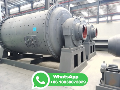
CERAMIC LINED BALL MILL. Ball Mills can be supplied with either ceramic or rubber linings for wet or dry grinding, for continuous or batch type operation, in sizes from 15″ x 21″ to 8′ x 12′. High density ceramic linings of uniform hardness male possible thinner linings and greater and more effective grinding volume.

Ball mill Wikipedia

Ball mill Wikipedia

A ball mill consists of a hollow cylindrical shell rotating about its axis. The axis of the shell may be either horizontal or at a small angle to the horizontal. It is partially filled with balls. The grinding media are the balls, which may be made of steel ( chrome steel ), stainless steel, ceramic, or rubber.

AMIT 135: Lesson 8 Rod Mills Mining Mill Operator Training

AMIT 135: Lesson 8 Rod Mills Mining Mill Operator Training

The product size distribution is narrower than a ball mill but significantly coarser. Most are overflow discharge type. Lengthtodiameter= to Mill length = 7 meters. Rod MillBall Mill Circuits Diagrams of mill circuits [image: (13582)]

CENTROID CNC Manuals and Documentation and Schematics

CENTROID CNC Manuals and Documentation and Schematics

Miscellaneous CNC Documents. Solid Model files for OAK, ALLIN1DC, PLCADD1616, DC1, ADD4AD4DA, Encoder Expansion Board. zip file. CNC console dimensions and mounting examples. CNC Standard Electrical Cabinet M400/M39/T400/T39. CNC Standard Electrical Cabinet M15 upgrade.

Mill Lubrication System | PPT SlideShare

Mill Lubrication System | PPT SlideShare

11. Lubricant Data: Masbate Gold Project's SAG mill uses Compounded Gear Oil as their main lubricant. But a different class of Gear oil is use in every operating system of the SAG mill. SAG Mill Components Type Characteristic Motor Bearings Omala 150 Gear oil. 150 viscosity at 40 C and 15 viscosity at 100˚C Gearbox Omala 320 Gear oil. 320 viscosity at 40˚C and 25 viscosity at 100˚C.

DIY Ball Mill Plans Homemade Rod Mill Drawing 911 Metallurgist

DIY Ball Mill Plans Homemade Rod Mill Drawing 911 Metallurgist

homemade ball mill plans. By this drawing, it is suggested that a typical homemade laboratory rod mill or ball mill might be fabricated from 20 cm (8 inches) diameter schedule40 type 316 stainless steel pipe and would be about 38 cm (15 inches) long.. The plans show stainless steel grinding rods for this size of mill may be a graduated charge from 25 to 10 mm diameter (1 inch to 1/2 inch) but ...

Ball Mill Working Principle And Main Parts GitHub Pages

Ball Mill Working Principle And Main Parts GitHub Pages

The main part of the ball mill mainly include feeding part, discharging part, a rotary part, a transmission part (reducer, small gear, motors, electrical control) and other parts. Hollow shaft adopts steel castings, the liner is detachable, slewing gear hobbing with casting, the cylinder body with wearresistant liner, with good resistance to wear.

Ball Mill for Cement Grinding Process

Ball Mill for Cement Grinding Process

Cement Ball Mill Structure. When Ball Mill is working, raw material enters the mill cylinder through the hollow shaft of the feed. The inside of the cylinder is filled with grinding media of various diameters (steel balls, steel segments, etc.); when the cylinder rotates around the horizontal axis at a certain speed, Under the action of centrifugal force and friction force, the medium and the ...

Grinding Circuit Control Strategy 911 Metallurgist

Grinding Circuit Control Strategy 911 Metallurgist

Figure 4 is a schematic diagram of a ball mill/cyclone control system. This diagram shows the instrumentation and the calculated variables used in the control strategies. The prior detailed process analysis study produced two major conclusions: Reduce mill feed size Reduce ball charge size

PID Material Handling Symbols and Their Usage Edraw Software

PID Material Handling Symbols and Their Usage Edraw Software

PID Material Handling Symbols and Their Usage. Predrawn PID material handling symbols represent ball mill, bulk bag feeder, bulk bag loader, cone crusher, dust collector, hopper, conveyor, grinder, shredder, silo, feeder, filter, wire mesh container, etc. Vector symbols help develop accurate and presentationquality diagrams and documentations.

Stirred Mill an overview | ScienceDirect Topics

Stirred Mill an overview | ScienceDirect Topics

Figure presents a schematic diagram of the Vertimill®. The screw rotates slowly such that the ball charge and slurry are not fluidized, but settle under gravity.

Free Process Flow Diagram PFD Templates SmartDraw

Free Process Flow Diagram PFD Templates SmartDraw

Quickly and easily model your business processes and make process flow diagrams with SmartDraw's process modeling software. Create PFDs, flowcharts, workflows and more with intelligent formatting and powerful automation. ... A process flow diagram (PFD), also known as a flowsheet, is a type of flowchart used by chemical and process engineers to ...

Chp Ppt Schematic Diagram Of Ballmill Crusher Mills

Chp Ppt Schematic Diagram Of Ballmill Crusher Mills

Nov 26, 2012 · working principle of ball mill with line diagram . coal grinding ball mill closed circuit diagram; . iron ore beneficiation plant ppt; ... Schematic diagram of C . Ball mill is widely used in mineral grinding mill industry. Electronics Mini Projects Circuit Diagram . Semester Electronics and Telecommunication ECE ...

Rod Mill | SpringerLink

Rod Mill | SpringerLink

End Peripheral Discharging Rod Mill. The end peripheral discharging rod mill feeds the material from one end through the mill journal, and discharges the grinding products from the other end of the mill to the adjacent ring groove with the help of a number of circumference holes (Fig. 2).The structure of end peripheral discharging rod mill is basically the same as that of overflow rod mill ...

Schematic diagram of a ball mill. | Download Scientific Diagram

Schematic diagram of a ball mill. | Download Scientific Diagram

Context 1 ... pharmaceutical ball mill is usually a cylindrical crushing device that is used for grinding of pharmaceutical powders by rotation around a horizontal axis. The device is partially...

PDF Module7 unit3 NSNT Module 7 Ballmilling INFLIBNET Centre

PDF Module7 unit3 NSNT Module 7 Ballmilling INFLIBNET Centre

Ballmilling Ball milling is an economic and facile technique to produce nanosized materials. It is a topdown approach of nanoparticle synthesis which includes mechanical breakdown of large substances into smaller one. It is used in producing metallic as well as ceramic nanomaterials. ... Figure 1 shows the schematics of ball milling. 3

Schematic Diagram of Ballmill Liming Heavy Industry Rock Crusher

Schematic Diagram of Ballmill Liming Heavy Industry Rock Crusher

Mill is widely used in the industrial production in one of the highfine grinding machinery, there are many types, such as a tubetype ballmill, a ballmill, ultrafine laminate mill, hand ballmill, horizontal ballmill, ballmill, the pad, energy saving ballmill, the overflow type ballmill, ceramic ball grid ballmill.

The schematic diagram of a ball mill driveline. ResearchGate

The schematic diagram of a ball mill driveline. ResearchGate

Download scientific diagram | The schematic diagram of a ball mill driveline. from publication: Electromechanical Dynamic Behaviour and StartUp Evaluation of Tumbling Ball Mills | This paper ...

Materials Development Using HighEnergy Ball Milling: A Review ... MDPI

Materials Development Using HighEnergy Ball Milling: A Review ... MDPI

Highenergy ball milling (HEBM) of powders is a complex process involving mixing, morphology changes, generation and evolution of defects of the crystalline lattice, and formation of new phases. This review is dedicated to the memory of our colleague, Prof. Michail A. Korchagin (), and aims to highlight his works on the synthesis of materials by selfpropagating hightemperature ...

Synthesis of nanomaterials using various topdown and bottomup ...

Synthesis of nanomaterials using various topdown and bottomup ...

Schematic diagram of ball milling technique. The temperature rises during milling attributable to balltopowder, balltowall collisions, balltoball collisions, and frictional forces. There are several reasons for the total temperature rise of particles during milling.

دریافت اطلاعات بیشتر